Contents
- Introduction to the problem of 3D printed parts not fitting together
- Design considerations for improving part fit
- Importance of slicer settings for improving print accuracy
- Quality control measures for identifying and addressing part fit issues
- Conclusion and summary of key takeaways for improving part fit in 3D printing.
- Frequently Asked Questions
Introduction to the problem of 3D printed parts not fitting together
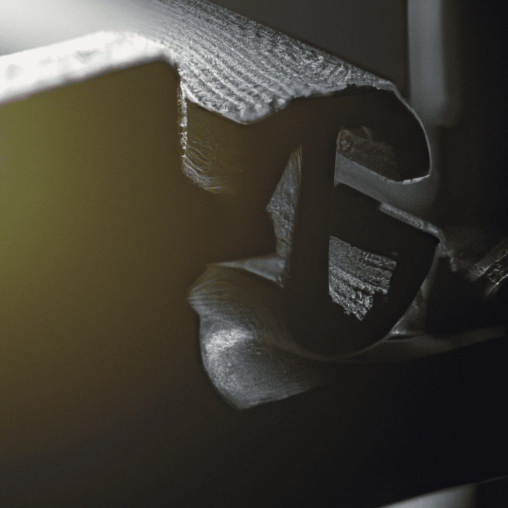
Adventures in 3D printing can be a challenge when parts don’t fit together correctly. The problem is often caused by design tolerances being too tight or loose. Slicing software and print accuracy can also be a factor.
To fix this, it’s important to set proper design tolerances and choose suitable slicing settings. Tight tolerances make parts too small, whereas loose tolerances introduce gaps. Plus, 3D printers need to be well-calibrated for accurate results.
Do a dry-fit test before final assembly to identify any size issues. Sandpaper or filing tools can help remove excess material for a better fit.
Engineering.com suggests measuring printed parts’ dimensions with micrometer calipers. Measure each component multiple times and record your findings.
Design and printing processes both require careful attention for successful 3D prints with great component fitment.
Design considerations for improving part fit
To improve the fit of 3D printed parts, you need to focus on design considerations. In order to achieve the desired results from your printed parts, you need to work on understanding the design tolerance concept and how to apply it. This will help you determine the required clearances and fits needed for your parts. You can also follow best practices for designing parts with proper clearances and fits, which can ensure better accuracy in printing.
Understanding design tolerance and how to apply it
Design Tolerance: A Pro Approach.
Design tolerance is an important factor in any manufacturing process. Knowing how it works and using it right can improve part fit and durability. Let’s look deeper.
Getting the Lowdown:
Tolerances are used to specify the allowed variation in dimensions, properties, or performance of a product. Designers use them to make sure parts match up specifically, decreasing the risk of mistakes and quality issues.
To understand design tolerance better, let’s look at its key elements in practice:
| Column 1 | Column 2 | Column 3 |
|---|---|---|
| Product | Limit Dimension | Tolerance(+/ -) |
| Bolt Size – M16 | 16mm | +/-0.02mm |
| O-Ring | Inner Dia-35mm | +/-0.1mm |
| Panel Thickness | 2.5mm | +/-0.15mm |
Unique Aspects:
Design tolerance changes depending on the part’s purpose, location, material, and the processes used to make it and assemble it.
Using Design Tolerance:
Here are some tips to correctly apply design tolerance:
- Use specific design and specs.
Why it works: This keeps everyone involved in the production process on the same page. - Consider safety factors when setting tolerances.
Why it works: Safety factors help avoid failure risks by predicting likely mistakes ahead of time. - Plan for worst-case scenarios when defining tolerances.
Why it works: Worst-case scenarios help identify production problems and make devices more reliable.
Conclusion:
Knowing about design tolerance leads to improved part fit and device stability during production processes. It also helps people use resources efficiently for different product designs. To ensure success from start to finish, designers must pay attention to all details – from component selection to assembly testing.
When it comes to part fits, ‘close enough’ should never be tolerated – or you’ll end up with parts flying off in unexpected directions.
Best practices for designing parts with proper clearances and fits
Designers should follow best practices to ensure optimal results when designing parts for proper clearances and fits. These include considering material properties, manufacturing processes, assembly requirements, and more.
Material Properties:
- Choose materials with suitable hardness and strength.
- Think about thermal expansion and corrosion resistance.
Manufacturing Processes:
- Pick processes that yield accurate parts.
- Account for post-processing that may be needed to achieve proper tolerances.
Assembly Requirements:
- Think about the order of assembly.
- Design parts that can be assembled without force or special tools.
Also, factor in part orientation and potential interferences between components. Examining these issues early on can help avoid costly delays and rework later.
One example of this is a client who had a pump system made with insufficient attention to detail. Tolerances were not properly considered, causing frequent leaks. After redesigning the parts with attention to details such as fitting sizes and material selection, they produced a functional product that met customer specifications.
Importance of slicer settings for improving print accuracy
To improve the print accuracy and part fit in 3D printing, it is crucial to understand the importance of slicer settings. Proper slicer settings can help you overcome the common challenges of design tolerance and achieve a better fit for the printed parts. In this section, we will provide an overview of common slicer settings and how they affect part fit. Additionally, we will offer some troubleshooting tips for fixing part fit issues in slicing software.
Overview of common slicer settings and how they affect part fit
Slicer settings have a huge effect on print accuracy. Knowing the common slicer settings and how they can affect part fit is essential for successful printing.
Check out the table below for some examples:
| Setting | Description | Impact on Part Fit |
| Layer Height | The thickness of each printed layer. | Affects smoothness, resolution and strength of prints. |
| Infill Density | The amount of interior structure material used in the print. | Affects strength, flexibility, and weight of prints. |
| Printing Speed | The speed at which the printer moves while printing. | Affects surface smoothness, detail level, and accuracy of prints. |
Also, adjusting temperature, support structures and wall thickness can have a huge impact on part fit.
A user once shared a story about how they achieved perfect print accuracy by tweaking slicer settings. After many attempts, they found the perfect combination for their specific needs. This shows us how important slicer settings are for optimal results. Do you think your slicer settings are great? Wait till your parts fit together like a kid’s jigsaw puzzle! Here’s how to make it happen.
Troubleshooting tips for fixing part fit issues in slicing software
Designing 3D prints requires slicer software. But, it can cause part fit issues due to incorrect slicing settings, printer calibration, and incompatible software versions. To help fix this, we have a six-step guide:
- Check slicing settings. Make sure layer height, infill, speed, and cooling fan are right for your design.
- Calibrate your printer bed. Use a sheet of paper as a gauge for the first layer and best adhesion.
- Check filament settings. Temperature and extrusion rate must be compatible with your printer.
- Inspect model quality. Look for gaps, holes, or missing modes that can cause part fit problems.
- Preview each layer. Many slicing software let you preview the thickness and position of the model.
- Experiment with slice settings. Try different settings through trial and error.
These measures help ensure successful 3D prints. Quality control helps you find the right fit.
Quality control measures for identifying and addressing part fit issues
To improve the quality of your 3D printed parts, it is essential to focus on identifying and addressing part fit issues. One of the most common reasons for part fit issues is the use of incorrect design tolerances during the designing phase. In this section, we will discuss quality control measures for ensuring accurate part fitment with sub-sections dedicated to inspection techniques for identifying issues before and after printing, and post-processing techniques to improve part fit after printing.
Inspection techniques for identifying issues before and after printing
When it comes to 3D printing part fit, various techniques must be used. This is to ensure high-quality standards are met throughout the production cycle.
- CAD Software: Designers create 3D models of parts to be printed. This lets them see potential issues which could arise during the actual print run.
- Pre-Printing Inspection: Printer operators inspect the printer and filament before beginning the print job. This helps them to prevent blockages and glitches.
- Post-Printing Inspection: After printing, inspections are done to spot any anomalies or defects. This includes size discrepancies or surface roughness.
To improve product quality, it’s important to calibrate machines, do regular maintenance checks and use high-quality raw materials. Through these techniques, manufacturers can consistently deliver parts with a superior fit and finish.
Pro Tip: Consistent quality control measures can help customers be satisfied. Plus, it saves time and money in inventory management.
Post-processing techniques for improving part fit after printing
To get the best fit of 3D printed parts, post-processing techniques are key. Here are six steps to use them:
- Check design and change if needed.
- Smooth rough parts with sandpaper or other materials.
- Fill gaps with epoxy or adjust tolerances.
- Add threaded inserts or snap-fit connections.
- Adhesive or weld seams for stability.
- Precise cuts for better alignment with laser cutter.
Remember the material – different adhesives or welding may be needed. And, investing in a high-quality printer and conducting quality control checks can minimize print errors and save time. Improving part fit with 3D printing is like a changing needle in a haystack.
Conclusion and summary of key takeaways for improving part fit in 3D printing.
To improve part fit in 3D printing, design tolerance, print accuracy, and slicing software must be considered. Adjusting these can help parts fit better. It is important to make sure the model dimensions are accurate and match the design specs. Also, print settings such as layer height, infill density, and cooling must be reviewed and modified.
Optimizing design before printing is key for high-quality prints with improved part fit. This helps avoid problems like overextrusion and underextrusion. Slight modifications may be needed when designing for 3D printing, such as testing different depths for holes or adjusting joint angles, to achieve precise fits.
Frequently Asked Questions
1. Why do my 3D printed parts not fit together?
There could be several reasons why your 3D printed parts do not fit together. One of the most common causes is the lack of design tolerance. Additionally, the slicing software used to prepare the 3D print may not have been configured accurately, leading to inaccuracies in the parts’ dimensions.
2. What is design tolerance, and why is it important?
Design tolerance refers to the acceptable amount of variation or deviation allowed in a part’s dimensions without affecting its fit or functionality. Adequate design tolerance is vital in 3D printing, as it prevents misalignments and insufficient clearances that may cause parts to not fit correctly.
3. How can I check the accuracy of my 3D printed parts?
You can use various measurement tools such as digital vernier calipers or micrometers to verify the accuracy of your 3D printed parts. If the dimensions of the parts do not match those specified in the original design file, then the slicing software used may have introduced inaccuracies during the printing process.
4. How can I improve the print accuracy of my 3D printer?
To enhance the print accuracy of your 3D printer, you can adjust the printer’s settings like the nozzle diameter, printing speed, and layer height. Additionally, calibrating the printer’s axes and ensuring that the printing bed is level will yield more precise prints.
5. Will changing the slicer’s settings improve part fit?
Changing a slicer’s settings can influence the accuracy and dimensions of 3D printed parts, but it is not always a guarantee. Furthermore, just tweaking the settings is not enough as some software settings may lead to the parts not fitting together. Therefore, it is advisable to check the settings thoroughly before printing.
6. Should I try to sand or file the parts to make them fit together?
Sanding or filing the parts may work in some instances, but it is generally not recommended that you resort to this method to fix 3D printed parts that do not fit together. It can significantly impact the parts’ structural integrity, making them weaker, and lead to potential malfunction. The best course of action is to assess the design tolerance and accuracy of the printer and its software settings and make necessary adjustments accordingly.